Before connecting cables to any of the internal headers or connectors, observe the precautions in “Before You Proceed”.
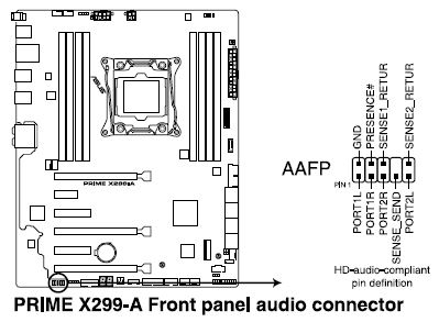
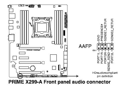
This connector is for a chassis-mounted front panel audio I/O module that supports either HD Audio or legacy AC`97audio standard. Connect one end of the front panel audio I/O module cable to this connector.
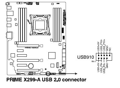
This connector is for USB 2.0 ports. Connect the USB module cable to this connector, then install the module to a slot opening at the back of the system chassis. This USB connector complies with USB 2.0 specification that supports up to 480 Mb/s connection speed.
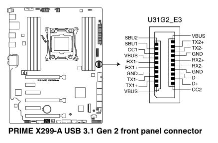
This connector allows you to connect a USB 3.1 Gen 2 module for additional USB 3.1 Gen 2 ports. The latest USB 3.1 Gen 2 connectivity provides data transfer speeds of up to 10 Gbps.
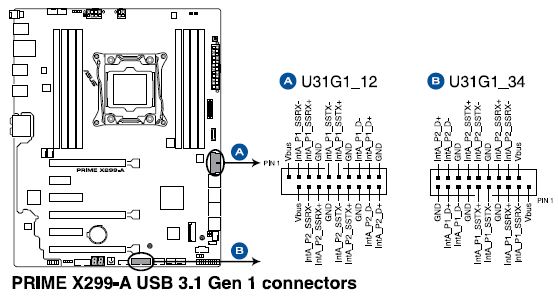
These connectors allow you to connect a USB 3.1 Gen 1 module for additional USB 3.1 Gen 1 front or rear panel ports. With an installed USB 3.1 Gen 1 module, you can enjoy all the benefits of USB 3.1 Gen 1 including faster data transfer speeds of up to 5 Gb/s, faster charging time for USB-chargeable devices,optimized power efficiency, and backward compatibility with USB 2.0.
 |
|
|
This connector is for a chassis-mounted front panel audio I/O module that supports HD Audio. Connect one end of the front panel audio I/O module cable to this connector.
|
|
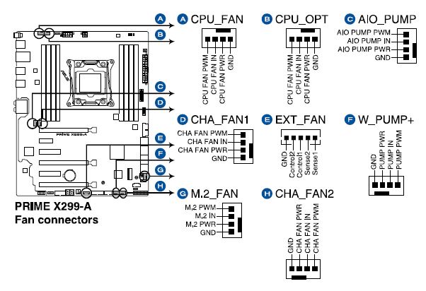
Connect the fan cables to the fan connectors on the motherboard, ensuring that the black wire of each cable matches the ground pin of the connector.
 |
|
|
|
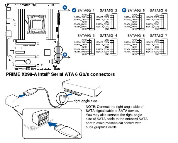
These connectors connect to Serial ATA 6.0 Gb/s hard disk drives using Serial ATA 6.0 Gb/s signal cables. You can create a RAID 0, 1, 5 or 10 configuration with the Intel® Rapid Storage Technology through the onboard Intel X299 chipset.
|
|
These connectors are for the serial (COM) port. Connect the serial port module cable to this connector, then install the module in a slot opening at the back of the system.

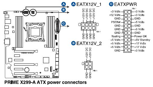
These connectors are for ATX power supply plugs. The power plugs are designed to fit these connectors in only one orientation. Find the proper orientation and push down firmly until the connectors completely fit.
Observe the precautions in "Before You Proceed".
Connect the 12 V processor core voltage power supply cable to the 8-pin connector (A).
Connect the main power supply cable to the 2 x 12 pin connector (C).
|
|
|
|
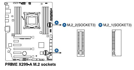
These sockets allow you to install M.2 SSD modules (purchased separately).
|
|
This connector supports several chassis-mounted functions.
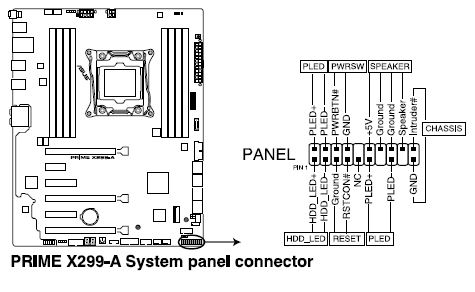
• System power LED (2-pin or 3-1 PLED)
This 2-pin or 3-pin connector is for the system power LED. Connect the chassis power LED cable to this connector. The system power LED lights up when you turn on the system power, and blinks when the system is in sleep mode.
• Hard disk drive activity LED (2-pin HDD_LED)
This 2-pin connector is for the HDD Activity LED. Connect the HDD Activity LED cable to this connector. The HDD LED lights up or flashes when data is read from or written to the HDD.
• System warning speaker (4-pin SPEAKER)
This 4-pin connector is for the chassis-mounted system warning speaker. The speaker allows you to hear system beeps and warnings.
• ATX power button/soft-off button (2-pin PWRSW)
This connector is for the system power button. Pressing the power button turns the system on or puts the system in sleep or soft-off mode depending on the operating system settings. Pressing the power switch for more than four seconds while the system is ON turns the system OFF.
• Reset button (2-pin RESET)
This 2-pin connector is for the chassis-mounted reset button for system reboot without turning off the system power.
Chassis intrusion connector (2-1 pin CHASSIS)
This connector is for a chassis-mounted intrusion detection sensor or switch. Connect one end of the chassis intrusion sensor or switch cable to this connector. The chassis intrusion sensor or switch sends a high-level signal to this connector when a chassis component is removed or replaced. The signal is then generated as a chassis intrusion event.
This connector is for the add-on Thunderbolt I/O card that supports Intel's Thunderbolt Technology, allowing you to connect up to six Thunderbolt-enabled devices and a DisplayPort enabled display in a daisy-chain configuration.

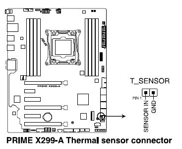
This connector is for the thermistor cable that allows you to monitor the temperature of your motherboard’s critical components and connected devices. Connect the thermistor cable and place the sensor on the device or the motherboard's component to detect its temperature.
 |
|
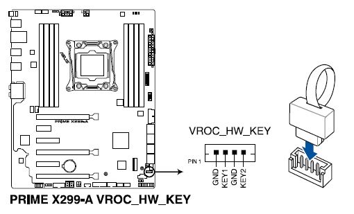
This connector allows you to connect a KEY module to enable CPU RAID functions with Intel CPU RSTe.
|
|